PS2 RPI4 Part IV: Conclusion
Multithreaded JavaScript has been published with O'Reilly!Three years have come and gone since my last post about the Raspberry Pi PlayStation 2 project. I completed the project sometime between then and now, closer to then, but never got around to writing about the final product. Well, here it is, the final product.
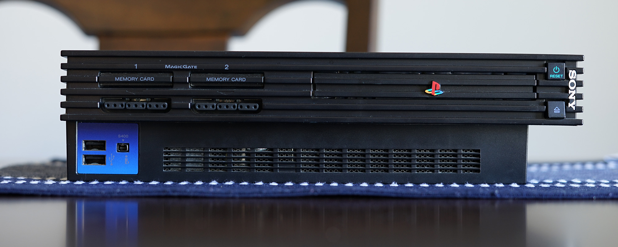
Not too interesting at this point. Surely, it mostly looks like a stock PlayStation 2. Note that the gunk on the rear right of the case was already there at the time that I found it in the dumpster. Instead, you're probably more interested in the internals.
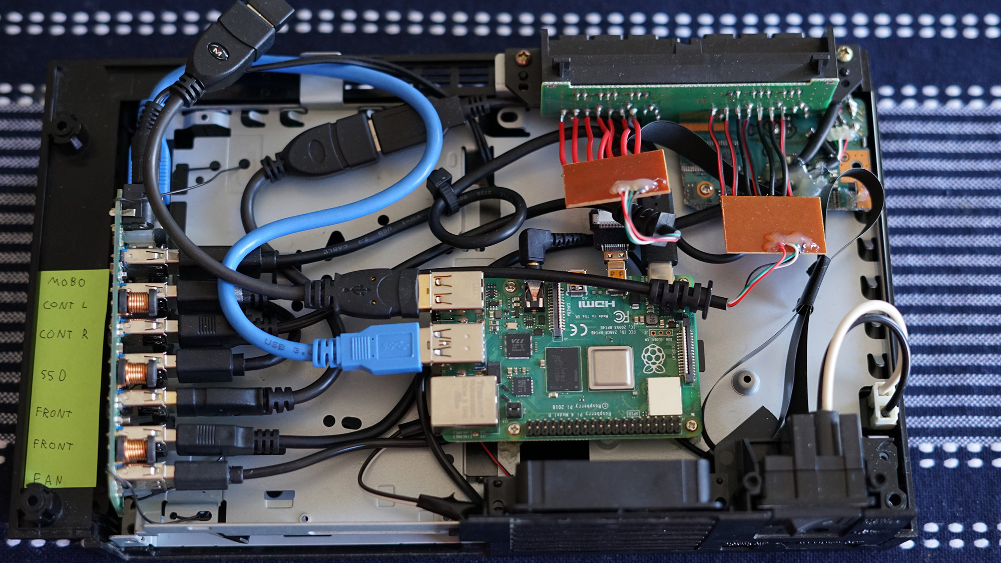
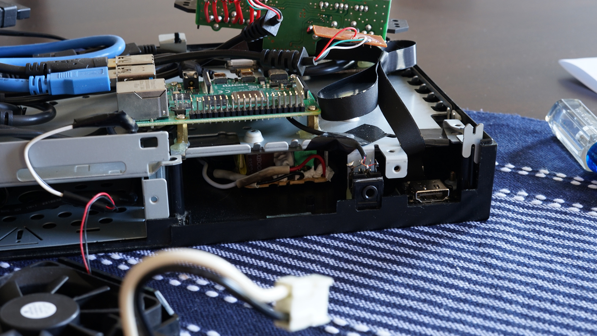
In the upper right corner are the two PlayStation 2 gamepad circuit boards, having a male USB on one end and originally a female PS2 port on the other end. The boards are very basic, having a blob chip, and seven contacts for the gamepads. For this project I dismantled the casing, discarded the female PS2 port, and then soldered each board to the PS2 gamepad circuits attached to the PS2 chassis. This allows the exterior to appear identical with all changes being internal.
Of course, I didn't really need to wire the gamepad ports up. But it seemed nice to be able to enable as many of the external ports as possible. One goal of the project was to use it for playing emulated videogames, and so by enabling the ports one can game using original PlayStation 2 controllers. Note that the memory card ports aren't wired up, since that's a bit too esoteric even for me, though there used to be USB peripherals to read the memory cards.
The Raspberry Pi itself is securely screwed into four brass standoffs that were then haphazardly attached to the metal plate using hot glue.
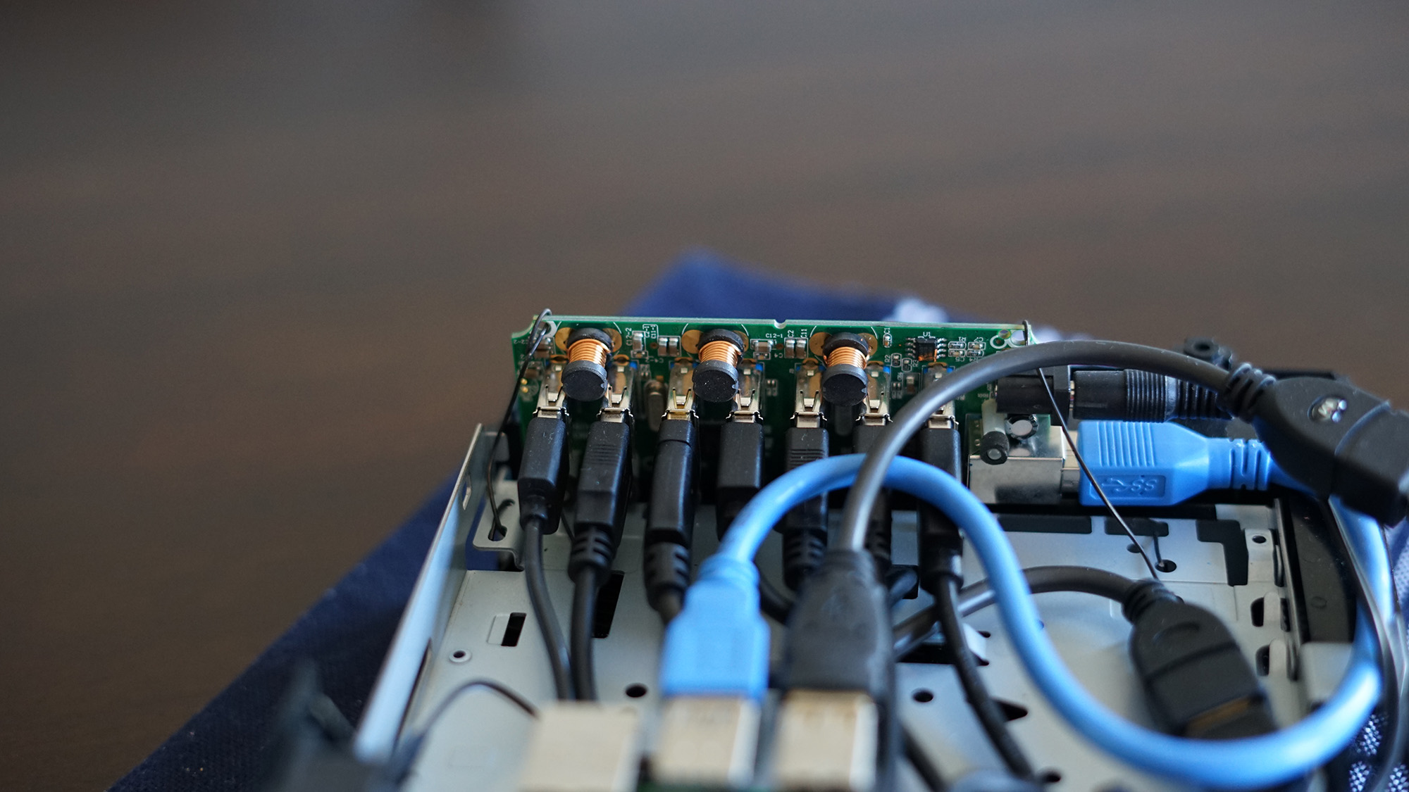
The lower left is the USB hub. Again, this was a consumer product that was then shelled for the project. It's a seven port USB-3 hub with a barrel jack for power. USB power delivery with a Raspberry Pi is always risky. Basically, if the Pi is expected to provide any power over USB, there's a chance too much power will be used and the board will become unstable. The Pi is plugged into the USB hub using a power-only line, and the USB hub is plugged into the Raspberry Pi using a data-only line (the blue cord).
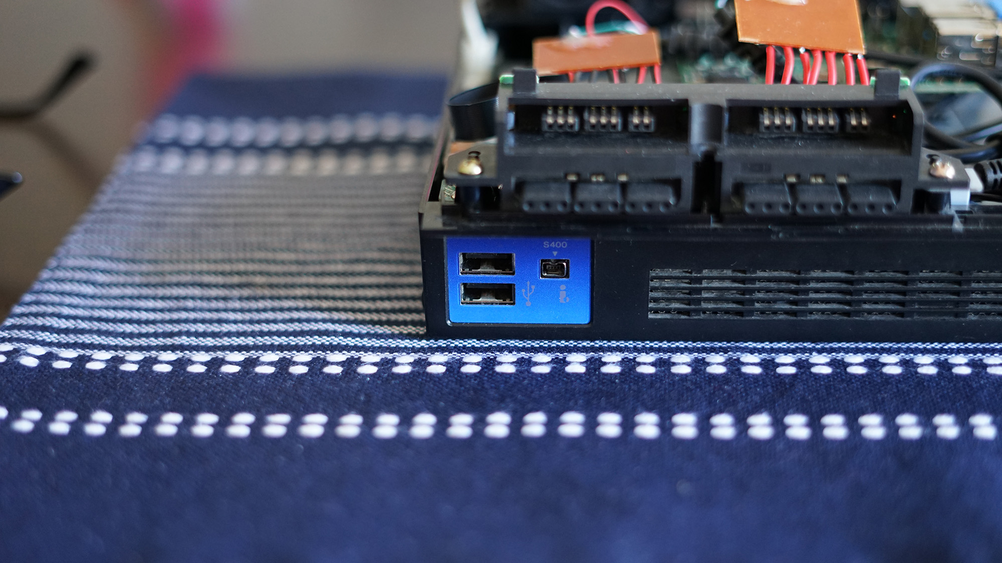
The front two USB ports are wired up as well. This was done by hacking up the motherboard, de-soldering all of the components, and soldering two spare male USB cords to the board. This is covered in Part III. On the plus side, the front of the case looks 100% authentic. On the minus side, the ports are only USB 2.0, and the motherboard needed to be destroyed. Also, note that the weird little port next to the USB ports isn't wired up. Not that one could find a peripheral to plug into it anyway…
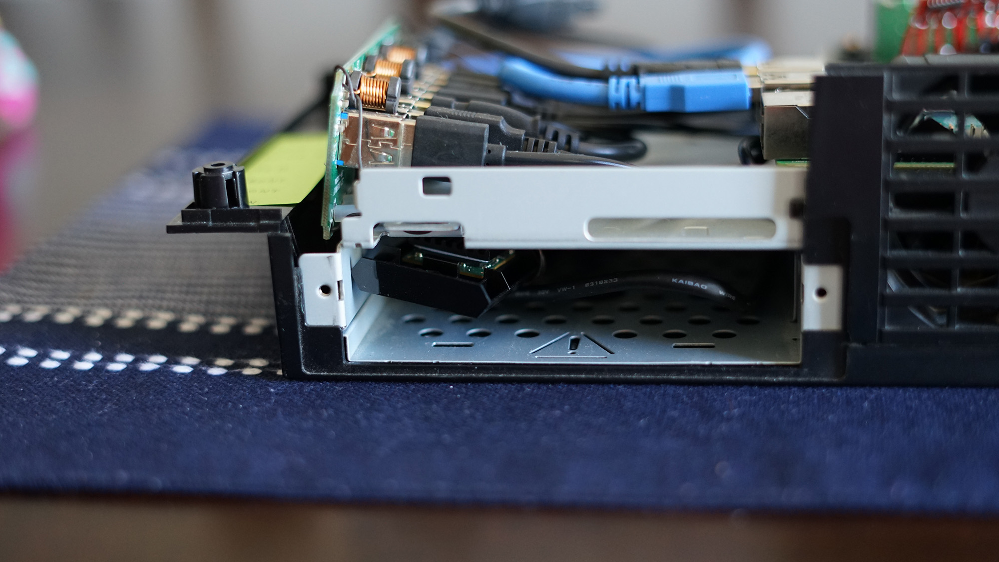
For permanent storage there's an SSD tucked beneath the metal plate in the bottom of the chassis. Again, this is using a USB-3 port, both for power and for data. The SSD originally had a metal case around it, but overall having components like this exposed is probably better for airflow. The wire for this is routed through one of the holes in the metal plate. Without the case the SSD is held to the circuit and some plastic by wrapping it in iron wire.
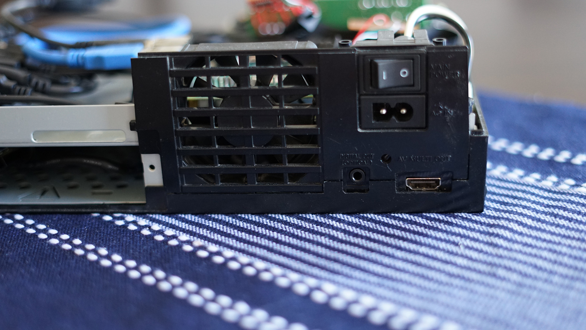
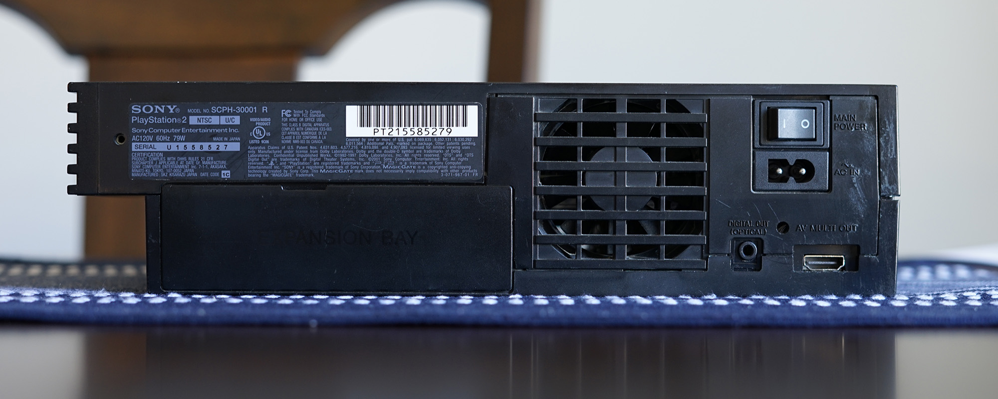
The rear of the case maintains the original power port and accompanying switch. This is how the device is powered on. The fan also works and is wired up to a USB male cord, providing 5v of power. I think the original fan required 7v or so but it works fine. Originally I wired it up through a GPIO port, but if something got jammed into the fan, I didn't want the Pi to short out. The fan is always running if the system is powered on.
The other parts of the rear IO aren't as straightforward.
The original S/PDIF and multiport ports weren't all that useful. Not many things use S/PDIF, and the multiport is certainly dead technology, outputting low quality analog signal. Plus, the two ports were attached to the motherboard, and would require complex circuitry to enable. While I could have hunted something down I instead chose to be more practical. In this case I bought a 3.5mm audio female jack, and an HDMI micro male / regular female / ribbon cable to wire it up.
The audio port is glued in place on the metal plate where it backed the S/PDIF port. The HDMI port is hot glued to the base of the plastic chassis. Both are backed with opaque black plastic to keep the insides of the case from being visible from the outside. The audio jack is soldered to a spare 3.5mm audio male jack and plugged into the Pi's audio port. The HDMI of course plugs into the Pi's HDMI jack.
For power, I disassembled the wall wort that came with the USB hub, and attached it to the bottom of the chassis beneath the metal plate. The A/C plug is soldered to heavy power wires which connect to the power switch component. The 12v D/C power output is then plugged into the USB hub, still using the same barrel jack.
Finally, there's also a small bluetooth-like dongle used for connecting to a remote control keyboard. It's on a USB extender and sits near the front of the case for better signal. It's basically the only peripheral sucking power from the Pi via USB but it's such low energy that it should be fine.
Admittedly, there is a lot going on, and it's a little hard to follow. So, here's a diagram:
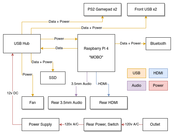
It's a real sleeper build. The front and sides are completely identical to the original case. The only difference is are the back S/PDIF to 3.5mm and the multiport to HDMI.
Sadly, the HDMI port drops frames, and really makes this thing impractical. It might be an issue with the ribbon cable length or with a bad port somewhere. The best fix might be to use a non-ribbon cable. It can't be used to play back movies since it visually glitches so much. The audio over 3.5mm doesn't sound the best. Instead, it might have made sense to incorporate a DAC inside of the case and expose an audio jack through that. The Pi's CPU is really showing its age, even when I built this three years ago, so it probably wouldn't be useful as any sort of server. Replacing this with something stronger like an Intel NUC might be best.
Also, I was never able to get the front power button, eject button, and LEDs to work, as that would require some circuit design that I'm not capable of. Wiring that up to power the device, and an LED to show that it's powered on, would be required to consider this project a success.
Overall it was fun to build and it certainly kept me entertained during the pandemic.
Thomas has contributed to dozens of enterprise Node.js services and has worked for a company dedicated to securing Node.js. He has spoken at several conferences on Node.js and JavaScript and is an O'Reilly published author.